Tower C, 2501, RNA NGECLAT, YAMUNA NAGAR, ANDHERI WEST. MUMBAI 400083

Tower C, 2501, RNA NGECLAT, YAMUNA NAGAR, ANDHERI WEST. MUMBAI 400083
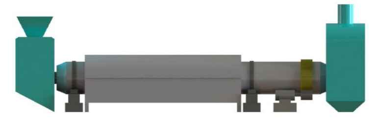
The Rotary Reactor (ATS) is designed to operate at high temperatures and with low levels of ambient air infiltration, very similar to a Rotary Kiln in Cement industries. The ATS is jacketed by another vessel which provides indirect heat to the material inside ATS for torrefaction.The reaction is a thermal decomposition of a portion of the material within the ATS without combustion of the material. There is a net energy loss that is recovered from the resulting off-gas (Torr Gas) which is combusted in the Burner system providing energy for the Torrefaction Reaction. The degree of energy provided by the Torr-gas is entirely dependent on the ratio of the species of material being processed, and on the operating temperature and dwell time within the system. Higher operating temperatures and longer dwell result in more thermal decomposition which provides higher energy density and more available energy fromTorr-gas but also results in a higher mass-loss of the material being processed.
The ATS is a fabricated steel drum mounted horizontally connected to the Inlet System at one end, and the Exhaust System at the other. It rotates around its horizontal axis running on integral steel tires and two pairs of trunnions that are mounted on the civil foundations.The drum contains a series of fixed flights. As material enters the rotating drum the flights scoop up the material and shower it across the width of the drum. Concentric inner flights catch the showering material as it falls, splitting the flow and re-showering the material.Hot gas is pulled through the drum by the Reactor ID fan and provides a kinetic energy that moves the showering material forward through the drum. Residence timeof the material in the drum can be controlled by a combination of rotation speed and ID Fan draft. This action also classifies material by size and density and has the effect of keeping larger pieces in the drum longer. Fines are blown through quickly, the end result being an even torrefaction of everything that passes through the drum. The showering material in the drum is an evenly dispersed resistive force to the gas; it heat sinks the energy in the gas and helps blend the gasas it travels through the drum.
The construction of the drum is modular. Sections are designed to enable easy transport to site and are bolted together on site. The tires are stress relieved and machined weldments and have a flange and web profile for maximum strength. The trunnions are over sized nodular iron castings that are slightly softer than the tires and are therefore designed to take damage before the (more expensive) tire. The tires are mounted externally and are bolted between drum sections. This creates a balanced beam thus minimizing stresses otherwise induced by extended spans.
The drum itself is a light weight, high strength concept. This is important to keep stress between the tires and trunnions at manageable levels without the use of exotic metallurgy.The strength comes from the use of channels and angles (bent the hard way) and welded to the inside of the drum shell. This keeps the shell round which adds significantly to the overall strength of the assembly.The complete structure is so rigid it can be mounted to the trunnions and, once correctly leveled,requires no counter-roller devices to maintain tracking. It is designed for the most extreme operating conditions. The drum drive is by roller chain that wraps around the drum, close to the outfeed end tire and running on sprocket teeth welded to the drum. The chain is driven by electric motor and gearbox and is constantly lubricated. Tire covers, chain guards and other safety guards are supplied to meet environmental, safety and operational considerations.
Have any questions?
+91 79001 99091Get in Touch: Contact Us for Expert Waste Management Solutions.